|
Master Thesis Code
by Simon Moser
|
Last updated: 17. April 2024
Since I know it motivates students, when I call pretty advanced mathematics "simple", "trivial" or "obvious", I try to do that as often as possible. (Not a real Quote, but close to what Dr. Franz Müller often said.)
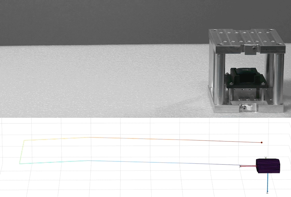
In this document the filter and smoother from the last document is extended to estimate 3D-Position. The EKF-RTS is first tested on simulated data from the JumpSensor and then on real data.
The movement is just the sensor mounted in the cube holder and then turned in such a way that every face of the cube is facing down at least once. The real movement where the sensor is mounted in the cube holder and the corresponding simulated movement is shown in the following animation.
The following derivation is strongly based on the last document. Whenever equations are the same, they are not well explained again.
The state vector is extended by the 3D-Position \(p\). Also, as mentioned in the last document, the sensitivity is removed. The resulting state vector is
\[ \mathbf{x} = \begin{bmatrix} \mathbf{q} & \prescript{g}{}{\mathbf{a}} & \prescript{g}{}{\mathbf{v}} & \prescript{g}{}{\mathbf{p}} & \prescript{s}{}{\boldsymbol{\omega}} & \mathbf{b}_a & \mathbf{b}_\omega & \mathbf{s}_a \end{bmatrix}^T \]
where \(\mathbf{q}\) are the four parts of the quaternion ( \( \mathbf{q} \in \mathbb{R}^{4 \times 1} \)), \(\prescript{g}{}{\mathbf{a}}\) is the acceleration ( \( \prescript{g}{}{\mathbf{a}} \in \mathbb{R}^{3 \times 1} \)), \(\prescript{g}{}{\mathbf{v}}\) is the velocity ( \( \prescript{g}{}{\mathbf{v}} \in \mathbb{R}^{3 \times 1} \)), \(\prescript{g}{}{\mathbf{p}}\) is the position ( \( \prescript{g}{}{\mathbf{p}} \in \mathbb{R}^{3 \times 1} \)), \(\prescript{s}{}{\boldsymbol{\omega}}\) is the angular velocity ( \( \prescript{s}{}{\boldsymbol{\omega}} \in \mathbb{R}^{3 \times 1} \)), \(\mathbf{b}_a\) is the accelerometer bias ( \( \mathbf{b}_a \in \mathbb{R}^{3 \times 1} \)), \(\mathbf{b}_\omega\) is the gyroscope bias ( \( \mathbf{b}_\omega \in \mathbb{R}^{3 \times 1} \)) and \(\mathbf{s}_a\) is the sensitivity of the accelerometer ( \( \mathbf{s}_a \in \mathbb{R}^{3 \times 1} \)).
This leads to the dimension of the state vector of \( n \times 1 = 25 \times 1 \).
We assume the initial state to be
\[ \mathbf{x}_0 = \begin{bmatrix} 1 & \mathbf{0}_{1 \times 21} & \mathbf{1}_{1 \times 3}\end{bmatrix}^T \]
In this section the state extrapolation model is described. We assume a constant angular velocity \( \prescript{s}{}{\boldsymbol{\omega}} \), a constant acceleration \( \prescript{g}{}{\mathbf{a}} \), and constant biases \( \mathbf{b}_a \) and \( \mathbf{b}_\omega \).
To keep the notation simple, the state transition function \( \mathbf{f} \) and the Jacobian \( \mathbf F \) of it are divided into subparts. The first part is the quaternion integration ( \( \mathbf{q}_{k+1} \)), the second part is about the position, velocity and acceleration ( \( \prescript{g}{}{\mathbf{p}}_{k+1}, \ \prescript{g}{}{\mathbf{v}}_{k+1} \) and \( \prescript{g}{}{\mathbf{a}}_{k+1}\)), the third part is about the angular velocity ( \( \prescript{s}{}{\boldsymbol{\omega}}_{k+1} \)), and the last part is about the biases and sensitivity ( \( \mathbf{b}_{a_{k+1}} \), \( \mathbf{b}_{\omega_{k+1}} \) and \( \mathbf{s}_{a_{k+1}} \)).
Therefore the state transition equation is
\begin{align*} \mathbf{x}_{k+1} &= \mathbf{f}(\mathbf{x}_k) \\[3mm] &= \begin{bmatrix} \mathbf{f}_1(\mathbf{q}_k, \prescript{s}{}{\boldsymbol{\omega}}_k) \hfill \\ \mathbf{f}_2(\prescript{g}{}{\mathbf{p}}_k, \prescript{g}{}{\mathbf{v}}_k, \prescript{g}{}{\mathbf{a}}_k) \hfill \\ \mathbf{f}_3(\prescript{s}{}{\boldsymbol{\omega}}_k) \hfill \\ \mathbf{f}_4(\mathbf{b}_{a_k}, \mathbf{b}_{\omega_k}, \mathbf{s}_{a_k}) \hfill \end{bmatrix}. \end{align*}
The Jacobian of the state transition function is
\begin{align*} \mathbf{F} &= \frac{\partial \mathbf{f}}{\partial \mathbf{x}} \\[3mm] &= \begin{bmatrix} \frac{\partial \mathbf{f}_1}{\partial \mathbf{x}} \hfill \\ \frac{\partial \mathbf{f}_2}{\partial \mathbf{x}} \hfill \\ \frac{\partial \mathbf{f}_3}{\partial \mathbf{x}} \hfill \\ \frac{\partial \mathbf{f}_4}{\partial \mathbf{x}} \hfill \end{bmatrix} = \begin{bmatrix} \mathbf{F}_1 \\ \mathbf{F}_2 \\ \mathbf{F}_3 \\ \mathbf{F}_4 \end{bmatrix}. \end{align*}
In contrast to the last document, the unlinearized quaternion integration is used. The quaternion integration is then
\begin{align*} \mathbf{q}_{k+1} &= \mathbf{f}_1(\mathbf{q}_k, \prescript{s}{}{\boldsymbol{\omega}}_k) \\[3mm] &= \left[ \cos \left( \frac{||\prescript{s}{}{\boldsymbol\omega}|| \Delta t}{2}\right) I_4 + \frac{1}{||\prescript{s}{}{\boldsymbol\omega}||} \sin \left( \frac{||\prescript{s}{}{\boldsymbol\omega}|| \Delta t}{2} \right) \boldsymbol\Omega(\prescript{s}{}{\boldsymbol\omega}) \right] \mathbf{q}_k, \end{align*}
with the operator matrix \( \boldsymbol\Omega(\prescript{s}{}{\boldsymbol\omega}) \) as defined in the last document
\[ \Omega(\prescript{s}{}{\boldsymbol\omega}) = \begin{bmatrix} 0 & -\prescript{s}{}{\omega}^T \\ \prescript{s}{}{\boldsymbol\omega} & - \lfloor \prescript{s}{}{\boldsymbol\omega} \rfloor_{\times} \end{bmatrix} = \begin{bmatrix} 0 & -\prescript{s}{}{\boldsymbol\omega_x} & -\prescript{s}{}{\boldsymbol\omega_y} & -\prescript{s}{}{\boldsymbol\omega_z} \\ \prescript{s}{}{\boldsymbol\omega_x} & 0 & \prescript{s}{}{\boldsymbol\omega_z} & -\prescript{s}{}{\boldsymbol\omega_y} \\ \prescript{s}{}{\boldsymbol\omega_y} & -\prescript{s}{}{\boldsymbol\omega_z} & 0 & \prescript{s}{}{\boldsymbol\omega_x} \\ \prescript{s}{}{\boldsymbol\omega_z} & \prescript{s}{}{\boldsymbol\omega_y} & -\prescript{s}{}{\boldsymbol\omega_x} & 0 \end{bmatrix}. \]
\[ \boldsymbol\omega = \begin{bmatrix} \omega_x \\ \omega_y \\ \omega_z \end{bmatrix} \in \mathbb{R}^{3 \times 1} \quad \longleftrightarrow \quad \begin{bmatrix} 0 \\ \omega_x \\ \omega_y \\ \omega_z \end{bmatrix} \in \mathbb{H}^{4 \times 1} = \boldsymbol\omega' \]
while for the sake of simplicity, we will use the same symbol \( \boldsymbol\omega \) for both.The Jacobian of the quaternion integration is
\begin{align*} \mathbf{F}_1 &= \frac{\partial \mathbf{f}_1}{\partial \mathbf{x}} \\[3mm] &= \begin{bmatrix} \mathbf{F}_{1,1} & \mathbf{0}_{4 \times 9} & \mathbf{F}_{1,2} & \mathbf{0}_{4 \times 9} \end{bmatrix}, \end{align*}
with the components
\[ \mathbf{F}_{1,1} = \frac{1}{|| \prescript{s}{}{\boldsymbol\omega} ||} \begin{bmatrix} \alpha & -\prescript{s}{}{\boldsymbol\omega}_x \beta & -\prescript{s}{}{\boldsymbol\omega}_y \beta & -\prescript{s}{}{\boldsymbol\omega}_z \beta \\ \prescript{s}{}{\boldsymbol\omega}_x \beta & \alpha & \prescript{s}{}{\boldsymbol\omega}_z \beta & -\prescript{s}{}{\boldsymbol\omega}_y \beta \\ \prescript{s}{}{\boldsymbol\omega}_y \beta & -\prescript{s}{}{\boldsymbol\omega}_z \beta & \alpha & \prescript{s}{}{\boldsymbol\omega}_x \beta \\ \prescript{s}{}{\boldsymbol\omega}_z \beta & \prescript{s}{}{\boldsymbol\omega}_y \beta & -\prescript{s}{}{\boldsymbol\omega}_x \beta & \alpha \end{bmatrix} \]
and
\[ \mathbf{F}_{1,2} = \frac{ \beta }{||\prescript{s}{}{\boldsymbol\omega}||} \begin{bmatrix} -q_1 & -q2 & -q3 \\ q_0 & -q3 & q2 \\ q3 & q0 & -q1 \\ -q2 & q1 & q0 \end{bmatrix}, \]
where
\begin{align*} \alpha &= \cos \left( \frac{||\prescript{s}{}{\boldsymbol\omega}|| \Delta t}{2} \right) \ ||\prescript{s}{}{\boldsymbol\omega}||, \\[3mm] \beta &= \sin \left( \frac{||\prescript{s}{}{\boldsymbol\omega}|| \Delta t}{2} \right). \end{align*}
Since the acceleration is assumed to be constant, the update is simply the propagation of the acceleration and the integration of the velocity and position. The state transition equation therefore is
\begin{align*} \begin{bmatrix} \prescript{g}{}{\mathbf{a}}_{k+1} \\ \prescript{g}{}{\mathbf{v}}_{k+1} \\ \prescript{g}{}{\mathbf{p}}_{k+1} \end{bmatrix} &= \mathbf{f}_2 \left(\prescript{g}{}{\mathbf{p}}_k, \prescript{g}{}{\mathbf{v}}_k, \prescript{g}{}{\mathbf{a}}_k \right) \\[3mm] &= \begin{bmatrix} \prescript{g}{}{a_x} \\ \prescript{g}{}{a_y} \\ \prescript{g}{}{a_z} \\ \prescript{g}{}{v_x} + \prescript{g}{}{a_x} \Delta t \\ \prescript{g}{}{v_y} + \prescript{g}{}{a_y} \Delta t \\ \prescript{g}{}{v_z} + \prescript{g}{}{a_z} \Delta t \\ \prescript{g}{}{p_x} + \prescript{g}{}{v_x} \Delta t + \frac{1}{2} \prescript{g}{}{a_x} \Delta t^2 \\ \prescript{g}{}{p_y} + \prescript{g}{}{v_y} \Delta t + \frac{1}{2} \prescript{g}{}{a_y} \Delta t^2 \\ \prescript{g}{}{p_z} + \prescript{g}{}{v_z} \Delta t + \frac{1}{2} \prescript{g}{}{a_z} \Delta t^2 \end{bmatrix}. \end{align*}
Since the above equation is linear, the Jacobian simply is
\begin{align*} \mathbf{F}_2 &= \frac{\partial \mathbf{f}_2}{\partial \mathbf{x}} \\[3mm] &= \begin{bmatrix} \mathbf{0}_{9 \times 4} & \mathbf{F}_{2,1} & \mathbf{0}_{9 \times 12} \end{bmatrix}, \end{align*}
with the component \( \mathbf{F}_{2,1} \) beeing a lower triangular matrix with the elements
\begin{align*} \mathbf{F}_{2,1} &= \begin{bmatrix} 1 \\ 0 & 1 \\ 0 & 0 & 1 & & & &\mathbf 0\\ \Delta t & 0 & 0 & 1 \\ 0 & \Delta t & 0 & 0 & 1 \\ 0 & 0 & \Delta t & 0 & 0 & 1 \\ \Delta t^2 & 0 & 0 & \Delta t & 0 & 0 & 1 \\ 0 & \Delta t^2 & 0 & 0 & \Delta t & 0 & 0 & 1 \\ 0 & 0 & \Delta t^2 & 0 & 0 & \Delta t & 0 & 0 & 1 \end{bmatrix}. \end{align*}
The angular velocity is assumed to be constant. Therefore the state transition equation simply is
\begin{align*} \prescript{s}{}{\boldsymbol\omega}_{k+1} &= \mathbf{f}_3(\prescript{s}{}{\boldsymbol\omega}_k) \\[3mm] &= \begin{bmatrix} \prescript{s}{}{\omega_x} \\ \prescript{s}{}{\omega_y} \\ \prescript{s}{}{\omega_z} \end{bmatrix} \end{align*}
with the obvious Jacobian
\begin{align*} \mathbf{F}_3 &= \frac{\partial \mathbf{f}_3}{\partial \mathbf{x}} \\[3mm] &= \begin{bmatrix} \mathbf{0}_{3 \times 13} & \mathbf{I}_3 & \mathbf{0}_{3 \times 9} \end{bmatrix}. \end{align*}
Similarly, the biases are assumed to be constant. Therefore the state transition equation obviously is
\begin{align*} \begin{bmatrix} \mathbf{b}_{a_{k+1}} \\ \mathbf{b}_{\omega_{k+1}} \\ \mathbf{s}_{a_{k+1}} \end{bmatrix} &= \mathbf{f}_4 (\mathbf{b}_{a_k}, \mathbf{b}_{\omega_k}, \mathbf{s}_{a_k}) \\[3mm] &= \begin{bmatrix} b_{a_{x_k}} & b_{a_{y_k}} & b_{a_{z_k}} & b_{\omega_{x_k}} & b_{\omega_{y_k}} & b_{\omega_{z_k}} & s_{a_{x_k}} & s_{a_{y_k}} & s_{a_{z_k}} \end{bmatrix}^T \end{align*}
with the obvious Jacobian
\begin{align*} \mathbf{F}_4 &= \frac{\partial \mathbf{f}_4}{\partial \mathbf{x}} \\[3mm] &= \begin{bmatrix} \mathbf{0}_{9 \times 16} & \mathbf{I}_9 \end{bmatrix}. \end{align*}
We have three measurements: the accelerometer, the gyroscope, and the velocity pseudo-measurement.
The three measurement models are derived separately as \( \mathbf{h}_1, \mathbf{h}_2, \) and \( \mathbf{h}_3 \). The complete measurement model is then
\begin{align*} \mathbf{h}(\mathbf{x}) &= \begin{bmatrix} \mathbf{h}_1(\mathbf{x}) \\ \mathbf{h}_2(\mathbf{x}) \\ \mathbf{h}_3(\mathbf{x}) \end{bmatrix} \end{align*}
with the Jacobian
\begin{align*} \mathbf{H} &= \frac{\partial \mathbf{h}}{\partial \mathbf{x}} \\[3mm] &= \begin{bmatrix} \mathbf{H}_1 \\ \mathbf{H}_2 \\ \mathbf{H}_3 \end{bmatrix}. \end{align*}
The true acceleration measured in the sensor frame is the sum of the gravity and the sensor acceleration, rotated into the sensor frame. Therefore, the hidden state is given by
\[ \prescript{s}{}{\mathbf{a}} = \prescript{s}{g}{\mathbf{R}_q(\mathbf{q})} \cdot (\mathbf{g} + \prescript{g}{}{\mathbf{a}}) = \prescript{s}{g}{\mathbf{R}_q(\mathbf{q})} \cdot \left( \begin{bmatrix} 0 \\ 0 \\ -g \end{bmatrix} + \begin{bmatrix} \prescript{g}{}{a_x} \\ \prescript{g}{}{a_y} \\ \prescript{g}{}{a_z} \end{bmatrix} \right), \]
where \( \mathbf{g} \) is the gravitational vector and \( \prescript{s}{g}{\mathbf{R}_q(q_k)} \) is the rotation matrix from the global frame to the sensor frame which is given by (Diebel, 2006)
\[ \prescript{s}{g}{\mathbf{R}_q(\mathbf{q})} = \begin{bmatrix} q_0^2 + q_1^2 - q_2^2 - q_3^2 & 2(q_1q_2 + q_0q_3) & 2(q_1q_3 - q_0q_2) \\ 2(q_1 q_2 - q_0 q_3) & q_0^2 - q_1^2 + q_2^2 - q_3^2 & 2(q_2 q_3 + q_0 q_1) \\ 2(q_1 q_3 + q_0 q_2) & 2(q_2 q_3 - q_0 q_1) & q_0^2 - q_1^2 - q_2^2 + q_3^2 \end{bmatrix}. \]
The measurement including the biases and sensitivity is then modelled as
\begin{align*} \mathbf{h}_1(\mathbf{x}) &= \mathbf{s}_a \circ \prescript{s}{}{\mathbf{a}} + \mathbf{b}_a \\[3mm] &= \mathbf{s}_a \circ \left (\prescript{s}{g}{\mathbf{R}_q(\mathbf{q})} \cdot (\mathbf{g} + \prescript{g}{}{\mathbf{a}}) \right) + \mathbf{b}_a. \end{align*}
The Jacobian of the accelerometer measurement model is then
\begin{align*} \mathbf{H}_1 &= \frac{\partial \mathbf{h}_1}{\partial \mathbf{x}} \\[3mm] &= \begin{bmatrix} \mathbf{H}_{1,1} & \mathbf{H}_{1,2} & \mathbf{0}_{3 \times 9} & \mathbf{I}_3 & \mathbf{0}_{3 \times 3} & \mathbf{H}_{1,3} \end{bmatrix}, \end{align*}
with the components
\begin{align*} \mathbf{H}_{1,1} &= \frac{\partial \mathbf{h}_1}{\partial \mathbf{q}} \\[3mm] &= \mathbf{s}_a \circ \left (2 \begin{bmatrix} \alpha q_0 + \beta q_3 - \gamma q_2 & \alpha q_1 + \beta q_2 + \gamma q_3 & \beta q_1 - \alpha q_2 - \gamma q_0 & \beta q_0 - \alpha q_3 + \gamma q_1 \\ \beta q_0 - \alpha q_3 + \gamma q_1 & \alpha q_2 - \beta q_1 + \gamma q_0 & \alpha q_1 + \beta q_2 + \gamma q_3 & \gamma q_2 - \beta q_3 - \alpha q_0 \\ \alpha q_2 - \beta q_1 + \gamma q_0 & \alpha q_3 - \beta q_0 - \gamma q_1 & \alpha q_0 + \beta q_3 - \gamma q_2 & \alpha q_1 + \beta q_2 + \gamma q_3 \end{bmatrix}\right), \end{align*}
and
\[ \mathbf{H}_{1,2} = \frac{\partial \mathbf{h}_1}{\partial \prescript{g}{}{\mathbf{a}}} = \mathbf{s}_a \circ \prescript{s}{g}{\mathbf{R}_q(\mathbf{q})}. \]
and
\begin{align*} \mathbf{H}_{1,3} &= \frac{\partial \mathbf{h}_1}{\partial \mathbf{s}_a} \\[3mm] &= \text{diag} \begin{pmatrix} \alpha (q_0^2 + q_1^2 - q_2^2 - q_3^2) &+& 2 \beta (q_0 q_3 + q_1 q_2) &-& 2 \gamma (q_0 q_2 - q_1 q_3) \\ -2 \alpha (q_0 q_3 - q_1 q_2) &+& \beta (q_0^2 - q_1^2 + q_2^2 - q_3^2) &+& 2 \gamma (q_0 q_1 + q_2 q_3) \\ 2 \alpha (q_0 q_2 + q_1 q_3) &-& 2 \beta (q_0 q_1 - q_2 q_3) &+& \gamma (q_0^2 - q_1^2 - q_2^2 + q_3^2) \end{pmatrix}. \end{align*}
where
\begin{align*} \alpha &= \prescript{g}{}{a}_x + g, \\ \beta &= \prescript{g}{}{a}_y + g, \\ \gamma &= \prescript{g}{}{a}_z + g. \end{align*}
The measurement modeled as the sum of the true angular velocity and the gyroscope bias simply is
\begin{align*} \mathbf{h}_2(\mathbf{x}) &= \prescript{s}{}{\boldsymbol\omega} + \mathbf{b}_\omega. \end{align*}
with the obvious Jacobian
\begin{align*} \mathbf{H}_2 &= \frac{\partial \mathbf{h}_2}{\partial \mathbf{x}} \\[3mm] &= \begin{bmatrix} \mathbf{0}_{3 \times 13} & \mathbf{I}_3 & \mathbf{0}_{3 \times 3} & \mathbf{I}_3 & \mathbf{0}_{3 \times 3} \end{bmatrix}. \end{align*}
The pseudo-measurement of the angular and translational velocity is equal to the hidden state. Therefore the measurement model is
\begin{align*} \mathbf{h}_3(\mathbf{x}) &= \begin{bmatrix} \prescript{g}{}{\mathbf{v}} \\ \prescript{s}{}{\boldsymbol\omega} \end{bmatrix}. \end{align*}
Therfore, the Jacobian simply is
\begin{align*} \mathbf{H}_3 &= \frac{\partial \mathbf{h}_3}{\partial \mathbf{x}} \\[3mm] &= \begin{bmatrix} \mathbf{0}_{3 \times 7} & \mathbf{I}_3 & \mathbf{0}_{3 \times 15} \\ \mathbf{0}_{3 \times 13} & \mathbf{I}_3 & \mathbf{0}_{3 \times 9} \end{bmatrix}. \end{align*}
This time, the process noise is modelled more accurately than in the last document, while the basic considerations remain trivial.
There are three main assumptions in the motion model:
Therefore, the process noise is moddeled with respect to the deviations from the assumptions which are defined as \( \sigma_{\omega} \), \( \sigma_{a} \), \( \sigma_{b_{\omega}} \), \( \sigma_{b_{a}} \) and \( \sigma_{s_{a}} \).
Since the physical processes are independent, the process noise covariance matrix can be written as three separate matrices aligned in a block diagonal matrix, where the complete process noise covariance matrix is
\[ \mathbf{Q} = \begin{bmatrix} \mathbf{Q}_{\omega} & & && \mathbf{0} \\ & \mathbf{Q}_{a} & \\ & & \mathbf{Q}_{\omega} & \\ & & & \mathbf{Q}_{b} \\ \mathbf{0} & & & & \mathbf{Q}_{s} \end{bmatrix}. \]
The process noise covariance matrix of the quaternion elements as a function of \( \sigma_{\omega} \) can be determined by projecting the angular velocity noise into the quaternion space (Becker, 2023, p. 168 ff.). Assuming a reduced state vector
\[ \mathbf{x}^* = \begin{bmatrix} q_0 & q_1, & q_2 & q_3 & \prescript{s}{}{\omega}_x & \prescript{s}{}{\omega}_y & \prescript{s}{}{\omega}_z \end{bmatrix}^T, \]
a matrix \( \mathbf{Q}_{\omega_0} \) can be defined as
\[ \mathbf{Q}_{\omega_0} = \text{diag} \begin{pmatrix} 0 & 0 & 0 & 0 & 1 & 1 & 1 \end{pmatrix} \cdot \sigma_{\omega}^2. \]
Using the linearized quaternion integration (see here), given as
\begin{align*} \mathbf{q}_{k+1} &= \mathbf{f}_\omega(\mathbf{q}_k, \prescript{s}{}{\boldsymbol{\omega}}_k) \\[3mm] &= \begin{bmatrix} \frac{2}{\Delta t} & -\prescript{s}{}{\omega}_{x_k} & -\prescript{s}{}{\omega}_{y_k} & -\prescript{s}{}{\omega}_{z_k} \\ \prescript{s}{}{\omega}_{x_k} & \frac{2}{\Delta t} & \prescript{s}{}{\omega}_{z_k} & -\prescript{s}{}{\omega}_{y_k} \\ \prescript{s}{}{\omega}_{y_k} & -\prescript{s}{}{\omega}_{z_k} & \frac{2}{\Delta t} & \prescript{s}{}{\omega}_{x_k} \\ \prescript{s}{}{\omega}_{z_k} & \prescript{s}{}{\omega}_{y_k} & -\prescript{s}{}{\omega}_{x_k} & \frac{2}{\Delta t} \end{bmatrix}\frac{\Delta t}{2} \begin{bmatrix} q_{0_k} \\ q_{1_k} \\ q_{2_k} \\ q_{3_k} \end{bmatrix}, \end{align*}
the process noise covariance matrix of the orientation is
\begin{align*} \mathbf{Q}_{\omega} &= \mathbf{f}_\omega \cdot \mathbf{Q}_{\omega_0} \cdot \mathbf{f}_\omega^T \\[3mm] &= \left( \frac{\Delta t \ \sigma_\omega}{2} \right)^2 \begin{bmatrix} q_{1_k}^2 + q_{2_k}^2 + q_{3_k}^2 & -q_{0_k} q_{1_k} & -q_{0_k} q_{2_k} & -q_{0_k} q_{3_k} \\ -q_{1_k} q_{0_k} & q_{0_k}^2 + q_{2_k}^2 + q_{3_k}^2 & -q_{1_k} q_{2_k} & -q_{1_k} q_{3_k} \\ -q_{0_k} q_{2_k} & -q_{1_k} q_{2_k} & q_{0_k}^2 + q_{1_k}^2 + q_{3_k}^2 & -q_{2_k} q_{3_k} \\ -q_{0_k} q_{3_k} & -q_{1_k} q_{3_k} & -q_{2_k} q_{3_k} & q_{0_k}^2 + q_{1_k}^2 + q_{2_k}^2 \end{bmatrix}. \end{align*}
Due to the property
\[ q_0^2 + q_1^2 + q_2^2 + q_3^2 = 1, \]
this simplifies to
\[ \mathbf{Q}_{\omega} = \left( \frac{\Delta t \ \sigma_\omega}{2} \right)^2 \begin{bmatrix} 1 - q_0^2 & -q_{0_k} q_{1_k} & -q_{0_k} q_{2_k} & -q_{0_k} q_{3_k} \\ -q_{1_k} q_{0_k} & 1 - q_1^2 & -q_{1_k} q_{2_k} & -q_{1_k} q_{3_k} \\ -q_{0_k} q_{2_k} & -q_{1_k} q_{2_k} & 1 - q_2^2 & -q_{2_k} q_{3_k} \\ -q_{0_k} q_{3_k} & -q_{1_k} q_{3_k} & -q_{2_k} q_{3_k} & 1 - q_3^2 \end{bmatrix}. \]
The process noise covariance matrix as a function of \( \sigma_{a} \) is quite straightforward. The process noise covariance matrix of the acceleration is
\[ \mathbf{Q}_{a} = \begin{bmatrix} 1 \\ 0 & 1 \\ 0 & 0 & 1 &&&& \ast\\ \Delta t & 0 & 0 & \Delta t^2 \\ 0 & \Delta t & 0 & 0 & \Delta t^2 \\ 0 & 0 & \Delta t & 0 & 0 & \Delta t^2 \\ \frac{\Delta t^2}{2} & 0 & 0 & \frac{\Delta t^3}{2} & 0 & 0 & \frac{\Delta t^4}{4} \\ 0& \frac{\Delta t^2}{2} & 0 & 0 & \frac{\Delta t^3}{2} & 0 & 0 & \frac{\Delta t^4}{4} \\ 0 & 0 & \frac{\Delta t^2}{2} & 0 & 0 & \frac{\Delta t^3}{2} & 0 & 0 & \frac{\Delta t^4}{4} \end{bmatrix} \sigma_a^2, \]
where \( \ast \) denotes the symmetric elements.
The process noise covariance matrix of the angular velocity is trivial and given by
\[ \mathbf{Q}_{\omega} = \text{diag}(\sigma_{\omega}^2, \sigma_{\omega}^2, \sigma_{\omega}^2). \]
The process noise covariance matrix of the biases is trivial and given by
\[ \mathbf{Q}_{b} = \text{diag}(\sigma_{b_{a}}^2, \sigma_{b_{a}}^2, \sigma_{b_{a}}^2, \sigma_{b_{\omega}}^2, \sigma_{b_{\omega}}^2, \sigma_{b_{\omega}}^2). \]
The process noise covariance matrix of the sensitivity is trivial and given by
\[ \mathbf{Q}_{s} = \text{diag}(\sigma_{s_{a}}^2, \sigma_{s_{a}}^2, \sigma_{s_{a}}^2). \]
We know the standard deviation of the accelerometer and gyroscope measurements due to the Allan variance. For the pseudo-measurement, we assume a very small standard deviation.
Therefore, the measurement noise covariance matrix is given by
\[ R = \text{diag} \begin{pmatrix} \sigma_{\text{acc}_{x,y}}^2 & \sigma_{\text{acc}_{x,y}}^2 & \sigma_{\text{acc_z}}^2 & \sigma_{\text{gyr}}^2 & \sigma_{\text{gyr}}^2 & \sigma_{\text{gyr}}^2 & \sigma_{\text{pseudo}}^2 & \sigma_{\text{pseudo}}^2 & \sigma_{\text{pseudo}}^2 \end{pmatrix}, \]
with \( \sigma_{\text{acc}_{x,y}} = 0.045 \), \( \sigma_{\text{acc_z}} = 0.07 \), \( \sigma_{\text{gyr}} = \frac{0.055 \pi}{180} \), and \( \sigma_{\text{pseudo}} = 10^{-9} \).
We assume that we know \( \mathbf{q}_0, \ \prescript{g}{}{\mathbf{a}_0}, \ \prescript{g}{}{\mathbf{v}_0}, \ \prescript{g}{}{\mathbf{p}_0}, \text{and} \prescript{s}{}{\boldsymbol\omega}_0 \). From the datasheet of the sensor, we know the standard deviation of the biases. Therefore, we assume that the initial covariance matrix is
\begin{multline*} \mathbf{P}_0 = \text{diag} ( \begin{matrix} \alpha & \alpha & \alpha & \alpha & \alpha & \alpha & \alpha & \alpha & \alpha & \alpha & \alpha & \alpha & \ldots \end{matrix} \\[3mm] \begin {matrix} \alpha & \alpha & \alpha & \alpha & \beta & \beta & \gamma & \zeta & \zeta & \zeta & \kappa & \kappa & \kappa \end{matrix})^{\circ 2}, \end{multline*}
where \( \alpha = 10^{-6} \), \( \beta = 0.6 \), \( \gamma = 0.8 \), \( \zeta = \frac{5 \pi}{180} \) and \( \kappa = 0.03 \), and \( A^{\circ 2} \) denotes that each element of a matrix \( A \) is squared (Hadamard power).
The zero velocity detection is done equally to the last document.
The EKF and RTS equations are identical to the ones derived in the previous section Part 4: Extended Kalman Filter. Please look them up there.
The Matlab implementation of this derivation is shown in derivation6Ekf6D.m.
The filter did not converge. The biases and sensitivities did converge to wrong values which led to a wrong estimation of the orientation which in turn led to a wrong estimation of the velocity and position.
If you think of it, this result makes sense: Imagin an orientation where the sensor doesn't move and the z-axis of the sensor is pointing downwards. All measured accelerations can be modeled as
\[ \prescript{s}{}{\mathbf{a}}_\text{meas} = \begin{bmatrix} \prescript{a}{}{a}_{x_\text{meas}} \\ \prescript{a}{}{a}_{y_\text{meas}} \\ \prescript{a}{}{a}_{z_\text{meas}} \end{bmatrix} = \begin{bmatrix} s_{a_x} \cdot 0 + b_{a_x} \\ s_{a_y} \cdot 0 + b_{a_y} \\ s_{a_z} \cdot g + b_{a_z} \end{bmatrix}. \]
There is no way to estimate the sensitivities \( s_{a_x}, s_{a_y} \quad \text \quad s_{a_z}\) and the biase \( b_{a_z} \) from this measurement. Only the two biases \( b_{a_x} \) and \( b_{a_y} \) can be estimated. Or, in other words, there are infinitely many biases and sensitivities that would fit the measurement. Therefore the filter does converge to a wrong solution. And then, as soon as a orientation or position change happens, the filter diverges.
Therefore, in the next derivation an algorithm is implemented that estimates the biases and sensitivities from the data. Then this estimation is used as an input for the filter. This way, the filter should converge.